
ТМГ32 transformers (energy-saving)
| Power: | 630 … 1600 kV·A |
| Voltage: | HV: 6 … 10.5 kV LV: 0.23 … 0.4 kV |
| Wiring diagrams and connection groups: | Yyn0 |
| Warranty: | 5 years |
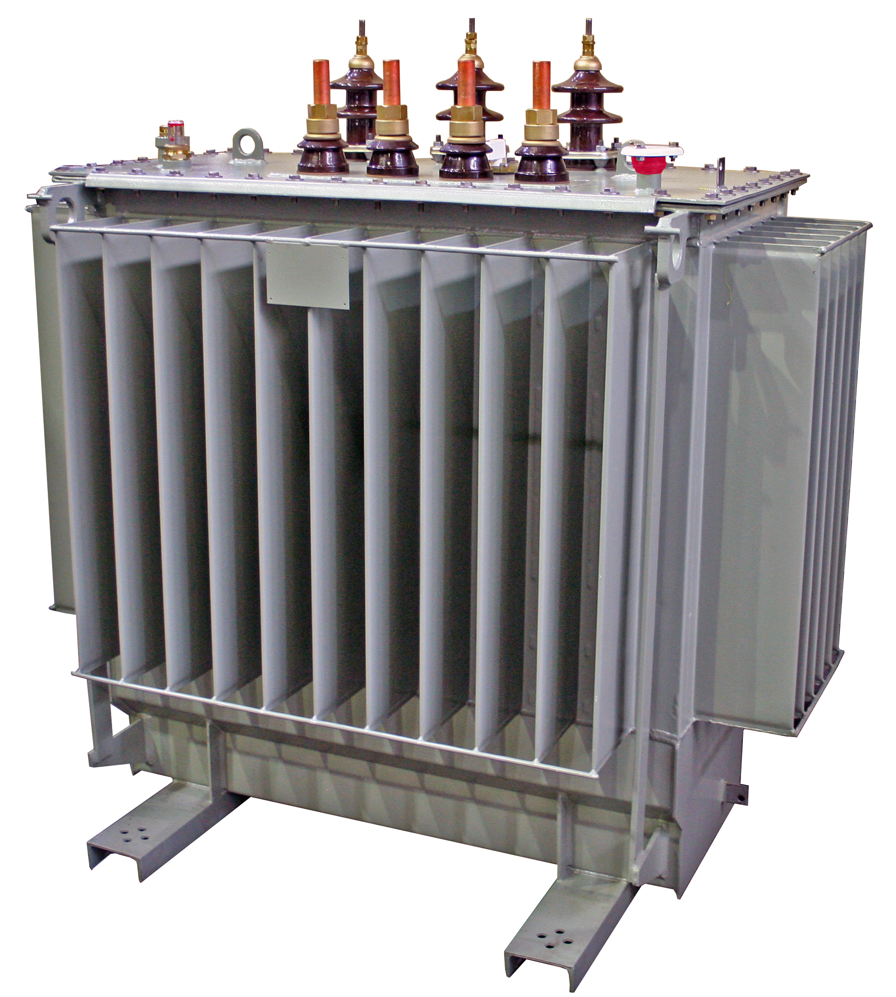
| Purpose: | Hermetic three-phase oil transformers without oil conservators are designed to convert electricity in the networks of power systems and electricity consumers. The level of no-load and short-circuit losses in this series of transformers complies with CENELEC recommendations. Structurally, the TMG32 transformer is made on the basis of a magnetic circuit with an oval rod (steel NV30S-120). HV windings are made of tape (foil) – the HV winding is made with a magnetically asymmetric adjustment circuit. The transformer tank is rectangular in plan, having corrugations on four sides. |


Production using a number of technical solutions that increase the reliability and reduce the operating costs of the TMГ series transformers
The level of no-load and short-circuit losses in this series of transformers complies with CENELEC recommendations.
Full testing during production
Solving urgent issues of energy conservation, we offer a new development – TMG32 transformers with a capacity of 630 … 1600 kV·A. The level of idling and short circuit losses in this series of transformers is set in accordance with the recommendations of the European Committee for Electrotechnical Standardization (CENELEC) and reduced (compared to transformers of other series, as well as transformers of other manufacturers), which can significantly reduce costs during operation of the equipment. At the same time, the noise characteristics of transformers are improved.
According to GOST 11677, the maximum deviations of the technical parameters of the transformers are: short-circuit voltage ± 10%; short circuit loss on the main branch + 10%; loss of idling + 15%; gross weight + 10%.
The low voltage winding of the transformers of this series is not made of aluminum wires, but of aluminum foil, which combines the simplicity of winding with a high level of reliability.
Structurally, the TMG32 transformer is made on the basis of a magnetic circuit with an oval shaft (NV30S-120 steel), LV coil made of aluminum tape (foil), and VN coil made of aluminum wire of APB grade. Due to the peculiarities of transformers with HV windings made of tape (foil), the HV winding is made with a magnetically asymmetric adjustment circuit. Transformer tank rectangular in plan having corrugations on four sides. To save oil, the bottom is made in the form “Trough”.
To control the oil level in the transformers, a float type oil indicator is provided.
To control the internal pressure in the tank and alarm if it exceeds the permissible values in the transformers placed in the room, an electrocontact manovacuum meter is provided for by the customer’s order.
To measure the temperature of the upper layers of oil on the transformer cover, a sleeve is provided for installing a liquid glass thermometer, which transformers are equipped with upon request of the consumer.
To measure the temperature of the upper layers of oil and control external electrical circuits, transformers designed for operation in a room or under a canopy are equipped with a manometric signaling thermometer by order of the consumer.
The neutral inlets and outlets of the LV transformer windings are designed for continuous load with a current equal to 100% of the rated voltage of the LV transformer winding.
Transformers are equipped with transport rollers for moving in both longitudinal and transverse directions.


